


One of the great benefits of the modular approach to synthesis is that each musician may choose from literally thousands of modules to build their own personal instrument. However, this diversity becomes a challenge when you want to write down notes describing your latest patch – either to share with others, or to recall later yourself. You can write down the connections and knob positions for each module, but what if you want to recreate a patch with a different set of modules?
Chris Meyer and I are not the first to note this problem. As far back as 1968, modular musicians and educators developed notation systems that described the audio generating, controlling, and processing blocks in an electronic music studio as a series of symbols, with lines interconnecting them instead of patch cables.
We decided to create a streamlined version of these symbols to describe patches throughout this book – both to show patches in the abstract, and to illustrate which extra functions are needed to complete a patch with a specific module.
Four groups of symbols
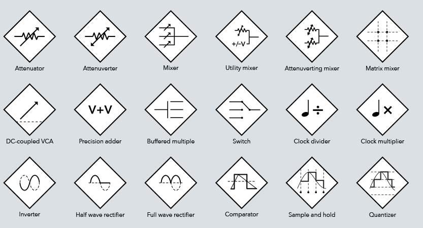
We’ve grouped the functions found in a modular synthesizer into four broad classes, each with a unique shape: The idea of this symbol language is to represent individual functions as opposed to entire modules.
One of the great things about modular synthesis is that you can often interchange the roles of different modules. For example, an ‘audio modifier’ such as a waveshaper with a low enough frequency response can be used to alter the modulation waveshape of a ‘CV source’ such as a low-frequency oscillator. Therefore, sometimes you will see the ‘wrong’ symbol such as an audio modifier in the middle of a CV modulation path.
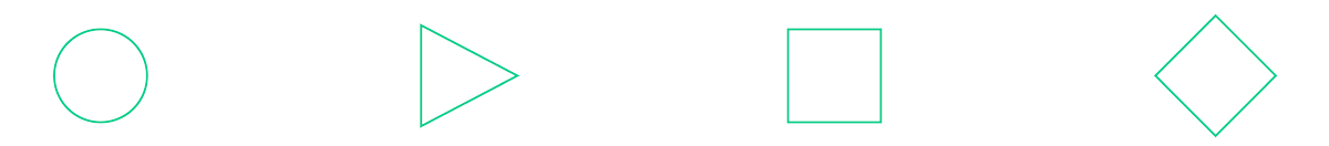
Audio sources
A circular symbol generates audio. This may be an oscillator, a noise source, a microphone, or a module that can play back previously recorded (‘sampled’) sounds.
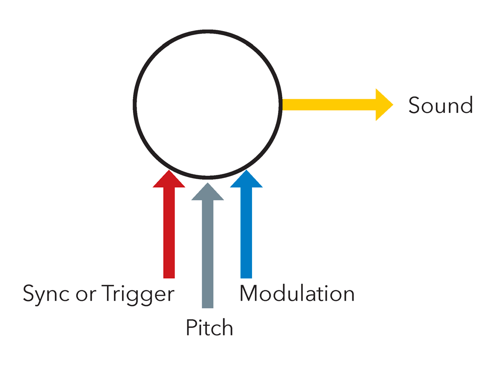
Modular audio sources – including oscillators, noise sources, sample players, and those that simulate real-world instruments and phenomena – are represented by a circle. The icon inside describes what general type of audio generator it contains; details will vary from module to module. Audio exits the right side of an Audio Source symbol; control signals – including pitch CVs, modulation CVs for the wave shape, and sync or trigger signals to restart playback – enter the bottom of the symbol.
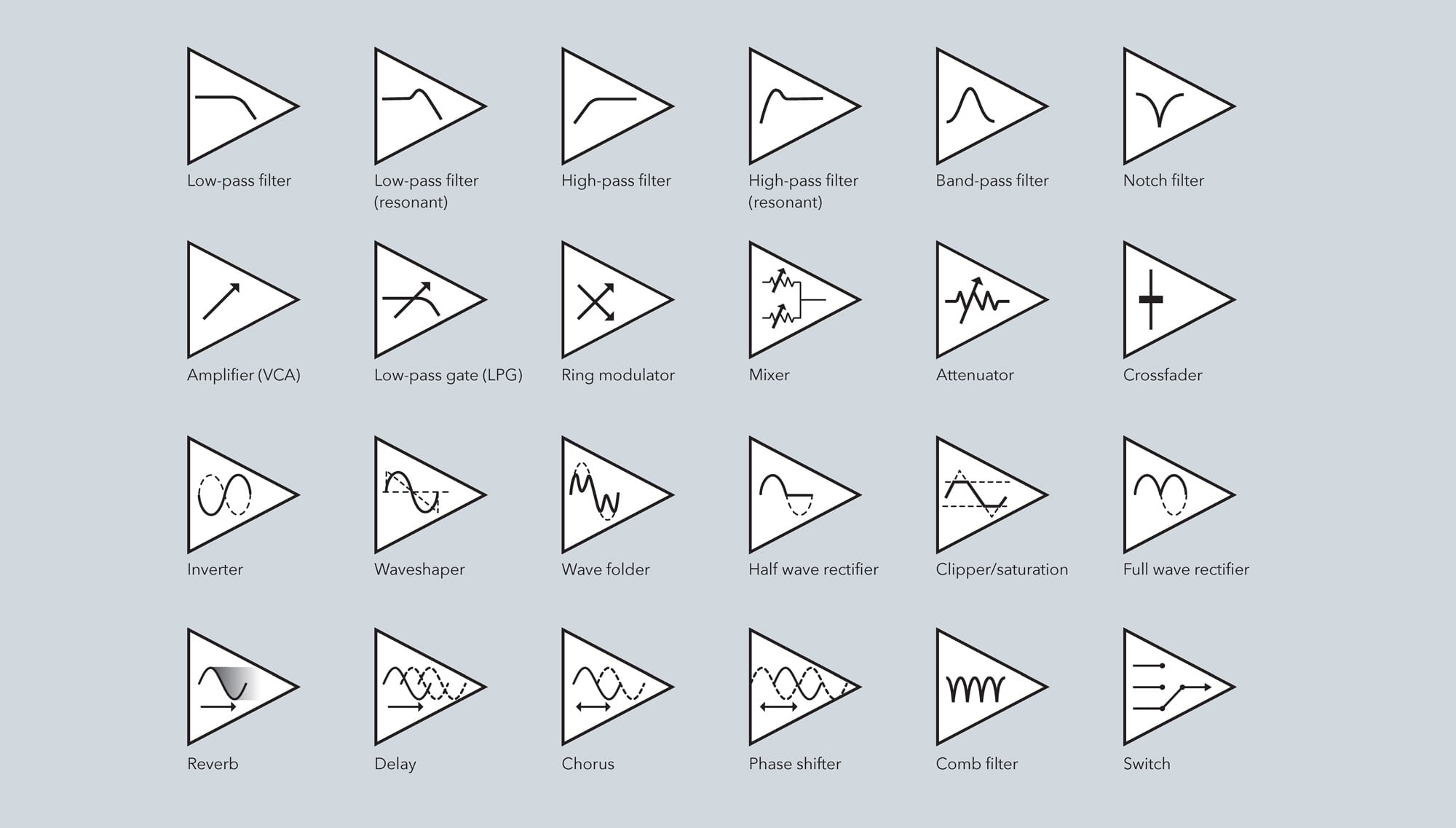
Audio modifiers
A triangular symbol modifies audio in some way. This may range from simply changing its level or mixing two sounds together, to altering its harmonic structure, to ‘effecting’ it by creating echoes or reverberations.
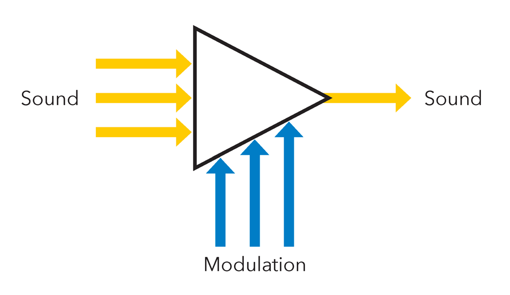
Functions that alter audio in some way – including filters and resonators, wave shapers, mixers, amplifiers, and effects – are represented by a triangle. Audio enters the left and exits the right side of an audio modifier symbol. A few modifiers – such as a mixer – may have multiple audio inputs; note that we use the same symbol regardless of the number of inputs connected. Control voltages that affect how the signal is changed enter the bottom of the symbol. It is not unusual for an audio modifier to also have more than one incoming control voltage, such as a filter’s cutoff frequency, resonance amount, and filter slope.
CV (Control voltage) sources
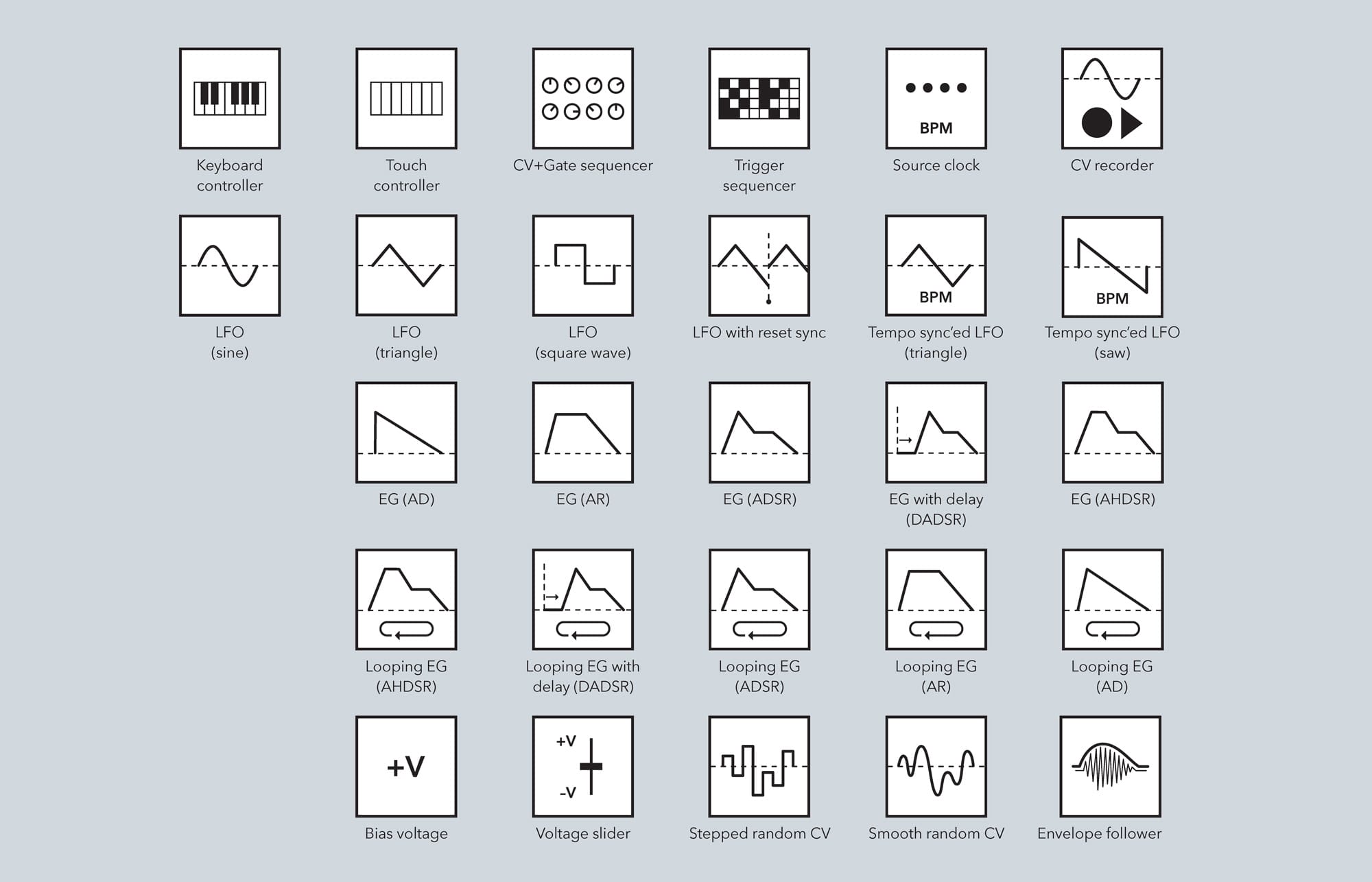
A square symbol generates a voltage used to control the operation of another module, such as the pitch voltage used to play different notes with an oscillator or to control how loud the audio should be passing through an amplifier.
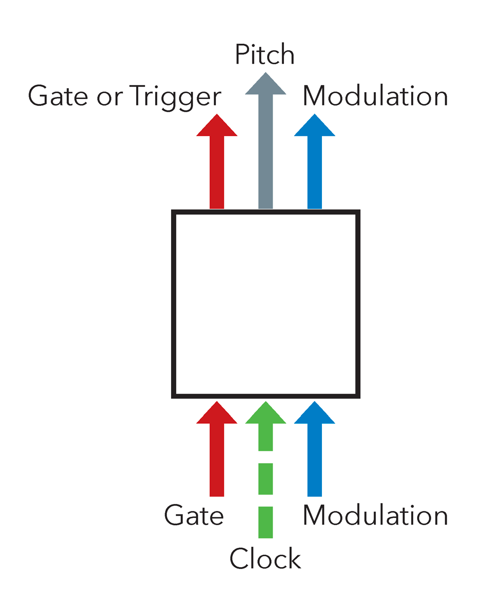
Devices that create a control voltage (CV) or a gate/ trigger signal – including keyboard controllers, sequencers, LFOs, envelope generators, and simple bias offset voltages – are represented by a square symbol. Note that there is some overlap with Audio sources; for example, noise or an oscillator may be used as a modulation control voltage or for the sound it produces. We will use the shape that best matches its function in a given patch. Gates, triggers, and control voltages exit at the top of a control voltage source symbol. Signals that may drive it enter at the bottom, as do any control voltages that affect its behavior.
CV (Control voltage) modifiers
A diamond-shaped symbol modifies a control voltage, in much the same way an audio modifier affects audio passing through it. In the case of a CV, you may want to smooth out the fluctuations in it, offset it by a specific amount or mix it with other CVs.
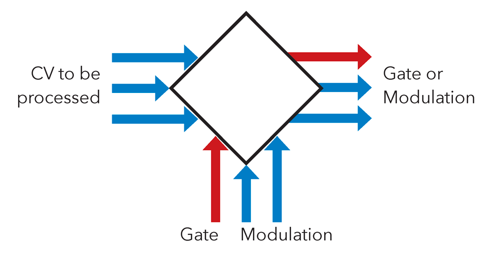
A diamond represents functions that alter a control voltage or gate/trigger – including attenuators, mixers, clock dividers, gate delays, and quantizers. Note that there is some overlap with Audio modifiers; for example, a voltage controlled amplifier (VCA) may be used to control the level of either audio or a control voltage. We will use the shape that best matches its function in a given patch. The CV or gate/trigger to be processed enters the left side of the symbol, and exits the right. Some functions such as a CV mixer or switch can have multiple inputs. CVs that affect the processing of the module, such as slew, delay time, or gates or triggers used to ‘sample’ the incoming voltage enter at the bottom.
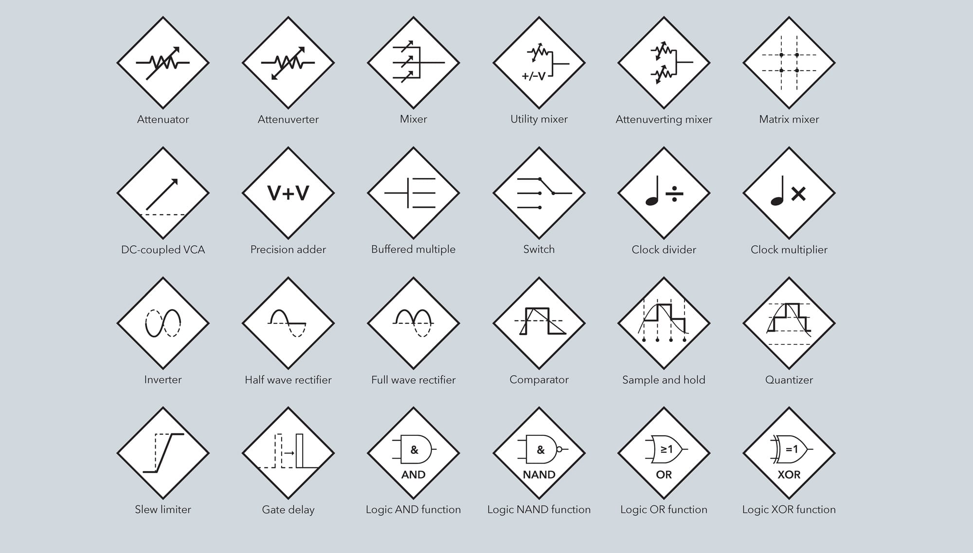
Details
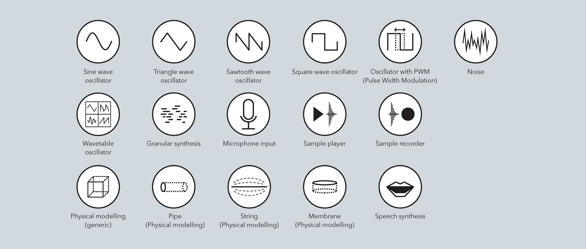
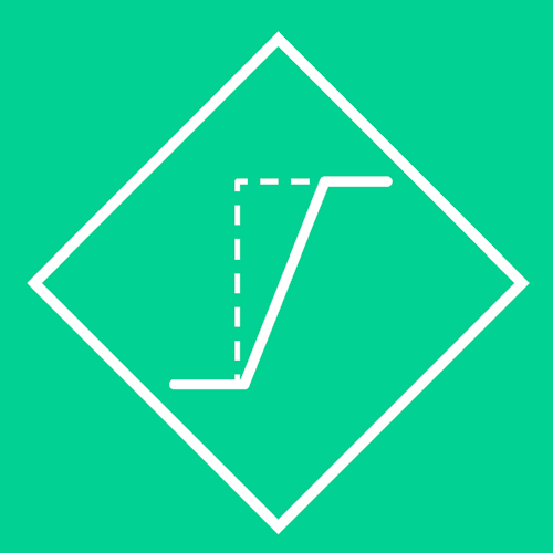
Inside each symbol shape is an icon that explains what function it performs. Our goal has been to use simple pictorial drawings rather than text in a specific language or scientific symbols to describe these functions. There can be infinite variations between the ways different functions perform: For example, one envelope generator may move in a straight line between target voltages; another may follow exponential or logarithmic curves between targets. For the sake of simplicity, we have used linear line segments in most of our icons. If you are hand-drawing a patch using this symbol language, you may add details such as the exact shape of an envelope.
If a patch calls on you to use a particular waveform output from an oscillator, we will use a circle (an Audio Source) with the shape of that wave inside it.
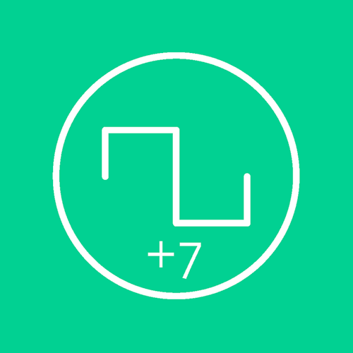
If the tuning of an oscillator is important – for example, if it should be transposed by a certain number of semitones or tuned to a specific note – we will add that detail inside the shape. Here is shown the symbol for a square wave oscillator that should be tuned 7 semitones (a perfect fifth) above the root note you want to play.

If the patch calls for a low-pass filter that attenuates the higher frequencies, we will use a triangle (an Audio Modifier) with a line bent downward as it moves to the right, approximating the frequency response of that filter.
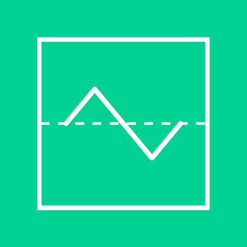
Some of the icons have dashed lines. These are often used to show where reference voltages or times are. For example, most low-frequency oscillators go both above and below 0 volts, so we will draw a dashed line through the center of the LFO’s waveform, contained inside the square symbol shape of a CV Source.

On the other hand, envelope generators tend to start from and return to 0 volts, so for those we draw the dashed line underneath their envelope shape.
Other times, the dashed line shows the original path of the voltage before that module has modified it. For example, a ‘lag’ or ‘slew limiter’ smoothes out sudden changes in voltage. Therefore, we use a dashed line showing a sudden rise in voltage, and a solid line showing the resulting smoothed-out transition, inside the diamond symbol for a CV Modifier.
Signal flow
Different module manufacturers may position the input, output, CV, and gate jacks almost anywhere on their front panels. For the sake of clarity, we use the following rules when drawing the lines that interconnect symbols:
Audio flows from left to right, plugging into the left side of the next module in line.
Control voltages, gates, and triggers flow from bottom to top, usually plugging into the bottom of the next module in line.
If a control voltage is to be processed, it will flow from left to right through that symbol, like an audio processor. CVs that affect that processing – such as the lag time in a slew limiter – enter the bottom of that symbol.
Most connections to symbols are obvious, such as pitch CV to the bottom of an oscillator. Where an input needs further explanation, we will add a small text note next to that connection.
Note that we use one symbol per function, even though a specific module may contain multiple functions. This helps us translate a patch between different collections of modules with different functions behind each front panel. For example, you may have a ‘combo’ module that contains two or more functions internally – such as a filter and a VCA – with no need for you to physically patch them together; we will use two symbols to represent this.
Different colors denote the functions of signals between modules. If you don’t have colors available when drawing patches, you can optionally note the type of signal beside the connection.
- Yellow = audio
- Gray = 1 V/oct pitch control voltages
- Blue = all other control voltages
- Red = triggers and gates
- Green (dashed) = primary clocks
Patch example
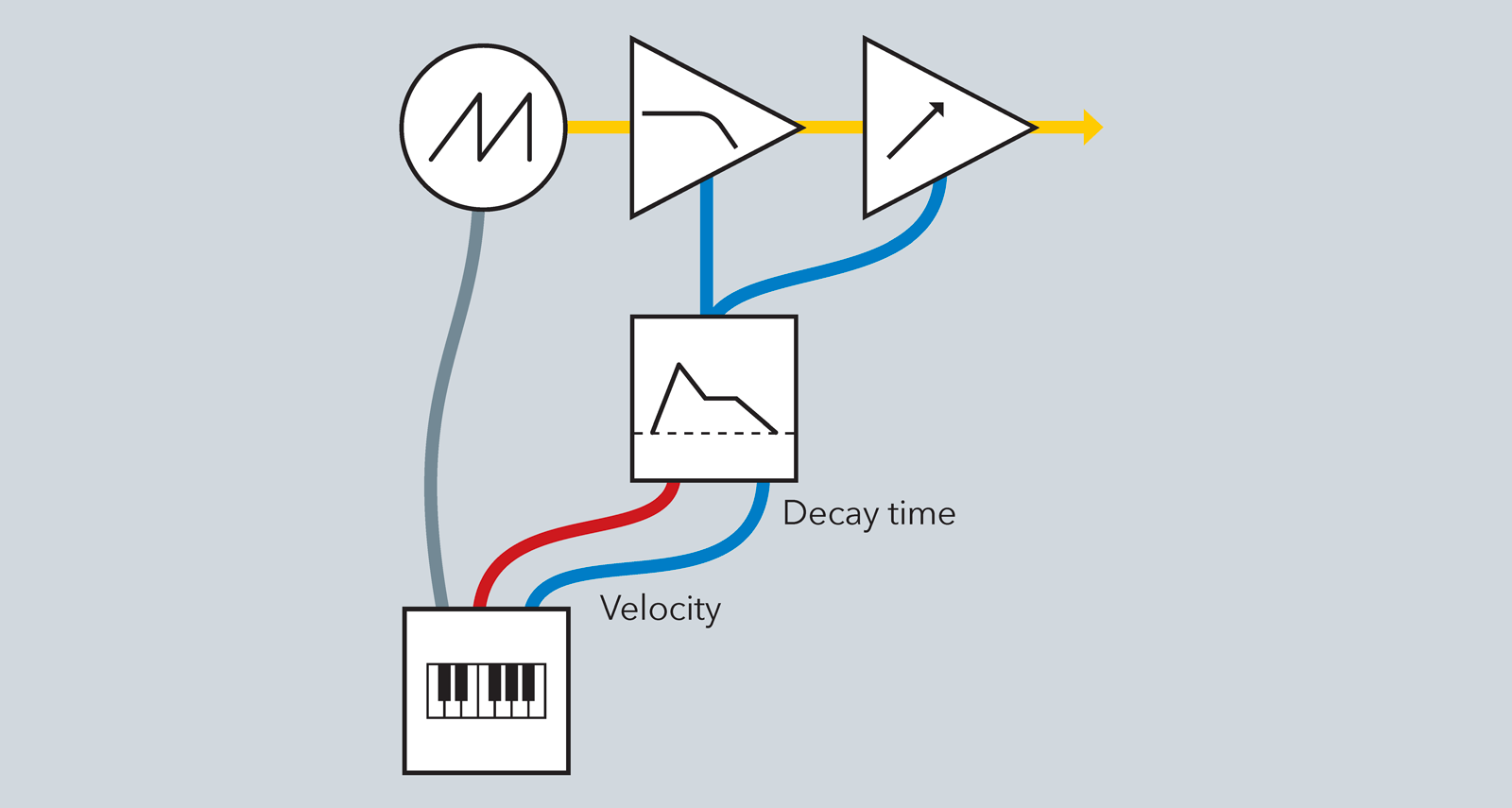
Now, let’s look at the example above using these symbols. In this patch, a keyboard controller sends pitch CV to a VCO, velocity CV to the release time of an envelope generator, and a gate to trigger that envelope generator. The VCO is patched through a lowpass filter and then a VCA. The same envelope generator drives both the filter’s cutoff frequency and the VCA’s volume.
Symbol history – where does this come from?
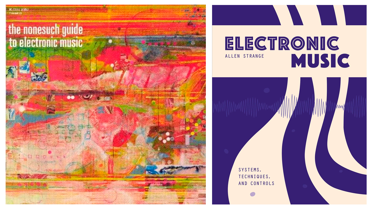
To create these patch symbols, we have built on the work of others. The earliest example of this symbolic language that we’ve seen is in the liner notes to the "Nonesuch Guide to Electronic Music" by Paul Beaver and Bernard Krause (1968). An alternate version of these symbols was created for Allen Strange’s book Electronic Music: Systems, Techniques, and Controls (1972; 1983) – here shown in a recent reprint issue. Beaver and Krause’s version was simplified by Richard Bugg for PAiA Electronics manuals in the early 1970s; Richard wrote an article explaining the system for Synapse magazine's March/April 1978 issue. Our work is an extension of Richard’s scheme. We were also inspired by the Serge Modular Music System manuals from the 1970s where Rich Gold combined front panel artwork with other graphics to describe patches for specific modules.
The symbols are available as open source files for download and use!
JOIN THE CLUB
Become a Pro Member to unlock all articles, interviews, podcast episodes, short documentaries, and more – including all seven ebooks (2000+ pages!). Discover, learn, and get inspired – wherever you are in your synth journey.


Comments